Voyager spacecraft structure
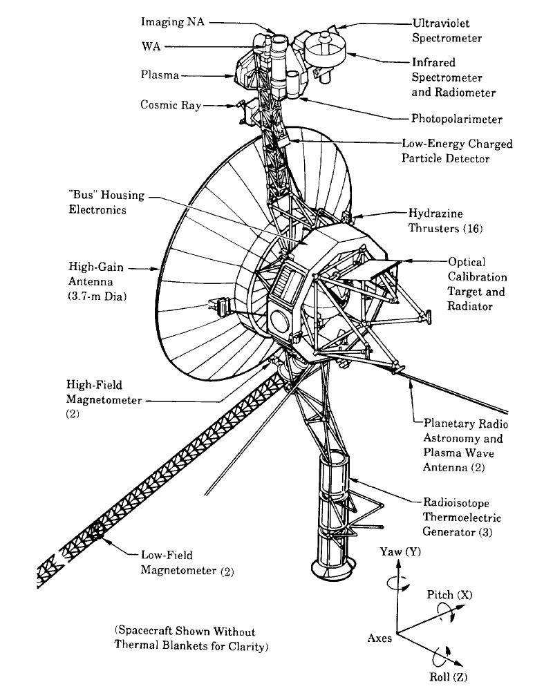
The 3.7 metre diameter high-gain antenna (HGA) is attached to the hollow ten-sided polygonal electronics bus, with the spherical tank within containing hydrazine propulsion fuel. The Voyager Golden Record is attached to one of the bus sides. The angled square panel to the right is the optical calibration target and excess heat radiator.
The three radioisotope thermoelectric generators (RTGs) are mounted end-to-end on the lower boom. The two planetary radio and plasma wave antenna extend diagonally downwards left and right. The 13 metre long Astromast tri-axial boom extends diagonally downwards left and holds the two low-field magnetometers (MAG); the high-field magnetometers remain close to the HGA.
The instrument boom extending upwards holds, from bottom to top: the cosmic ray susbsystem (CRS) left, and Low-Energy Charged Particle (LECP) detector right; the Plasma Spectrometer (PLS) right; and the scan platform that rotates about a vertical axis.
The scan platform comprises: the Infrared Interferometer Spectrometer (IRIS) (largest camera at top right); the Ultraviolet Spectrometer (UVS) just above the UVS; the two Imaging Science Subsystem (ISS) vidicon cameras to the left of the UVS; and the Photopolarimeter System (PPS) under the ISS.
Suggested for English Wikipedia:alternative text for images: A space probe with squat cylindrical body and a large parabolic radio antenna dish pointing left, a three-element radioisotope thermoelectric generator on a boom extending down, and scientific instruments on a boom extending up. A disk is fixed to the body facing front left. A long tri-axial boom extends down left and two radio antenna extend down left and down right.Yderligere oplysninger om licens til billedet kan findes her. Sidste ændring: Fri, 19 Apr 2024 15:35:32 GMT